2. 玉林师范学院物理与电子工程技术系,广西玉林 537000
2. School of Physics and Telecommunication Engineering, Yulin Normal University, Yulin, Guangxi, 537000, China
在材料的加载和加工制备过程中会不可避免地产生纳米或微米裂纹[1]。纳米尺度的裂纹强烈地依赖于纳米缺陷结构,包括位错、向错、纳米裂纹和纳米孔洞等[2]。材料的断裂通常分为脆性断裂和韧性断裂[3],分别对应于裂纹的脆性或韧性扩展。裂尖发射位错在材料的韧-脆转变中起关键作用[4, 5],同时也对裂纹扩展模式产生重要影响。固态晶体材料在裂尖发射一定数量的位错后可以发生解理。Rice[6]指出,在脆性裂纹扩展的过程中,裂尖不发射位错。然而,Argon[7]发现裂纹在脆性解理扩展之前可以有少量的位错从裂尖发射,认为硅晶体的韧-脆转变取决于有多少位错从裂尖发射。Yashiro[8]认为有效应力强度因子的增强归因于裂尖位错的发射。在韧性材料的裂纹扩展过程中,裂尖发射位错的过程中不发生钝化[9]。虽然目前已经有许多基于宏观断裂力学的研究成果,但是仍然缺乏纳观尺度上裂纹扩展行为的深度报道[10]。
在微观和纳观尺度,依据裂纹的形核机理和裂纹扩展形貌,可以将裂纹分为两类[11]:一类是Griffith裂纹,另一类是Zener裂纹。Griffith裂纹是存在固体中的裂纹,它不能很好地解释金属中的裂纹形核。Zener裂纹有一个尖端和一个钝端,裂纹总是从尖端扩展,它能够更好地描述金属中的裂纹形核[11-13]。目前,关于Griffith裂纹的研究已有很多报道,而关于Zener裂纹的研究报道仍很少[12]。Fan等[13, 14]研究了Zener-stroh裂纹(Zener裂纹)与包覆粒子的相互作用,认为Zener-stroh裂纹在异质材料的界面形核。Wu[15]从能量的角度建立楔型Zener裂纹的物理模型,研究了楔型Zener裂纹与晶界位错的相互作用,并计算了Zener裂纹裂尖处的楔型偶极子的精确解。Zhuang等[16]分析了平行于涂层与垫底截面的Zener-stroh裂纹(Zener裂纹)的弹-塑性应力。最近,Wu等[17, 18]通过求解能量平衡方程,讨论了楔型向错偶极子对Zener裂纹形核的影响。Wang等[19]研究了向错引起的Zener裂纹,表明向错长度、弹性失配都会对Zener裂纹的形核产生影响。虽然已经有少量有关Zener裂纹的研究,但是目前仍然缺乏在纳观尺度上对Zener裂纹形核与扩展的详细研究。
随着计算机技术的快速发展,已有许多计算模拟方法在裂纹扩展中得到广泛应用,其中在原子尺度上对裂纹形核扩展研究的分子动力学取得较多的成果[20-22],但仍存在较大的时间尺度局限性[23]。2004年Elder等[24]提出的原子级晶体相场(PFC)模型,能够在原子尺度上捕捉金属的弹-塑性外延特征行为,已广泛应用于材料微结构演化的众多领域[25-32]。PFC模型的时间尺度与实际的缺陷运动的迁移时间尺度相符,施加的应变率量级也与实验结果相符[25],因此能够更好地反映裂纹原子尺度运动的微观细节。针对不同空间尺度的微结构计算,可根据图 1所示的几种主要数值计算方法进行。本文系统地报道了本课题组近几年应用PFC方法研究Zener裂纹形核扩展过程的韧-脆转变、孔洞裂纹的愈合修复,以及相关机理研究等方面的最新成果,并指出今后的研究方向和重点关注的问题。

|
| 图 1 不同空间尺度的微结构的主要数值计算方法 Fig. 1 Several main numerical calculation methods for microstructures of different spatial scales |
1 PFC模型 1.1 原始的PFC模型
Elder等[24]提出的PFC模型,其物理含义明晰,能够更合理地描述微观缺陷。PFC模型的自由能函数如式(1)所示:
| $ F= \int \mathrm{d} V\left\{\frac{\mathit \Phi}{2}\left[a+\lambda\left(q_0^2+\nabla^2\right)^2\right] \mathit \Phi+g \frac{\mathit \Phi^4}{4}\right\}, $ | (1) |
式中,
| $ \frac{\partial \rho}{\partial \tau}=\nabla^2 \frac{\delta F}{\delta \rho}, $ | (2) |
式中, ρ为无量纲原子密度函数,τ为无量纲时间。为使PFC模型的自由能函数的参数尽量少,可对式(1)进行无量纲处理,得到无量纲的自由能函数,如式(3)所示:
| $ F=\int\left\{\frac{\rho}{2}\left[\gamma+\left(1+\nabla^2\right)^2\right] \rho+\frac{\rho^4}{4}\right\} \mathrm{d} V, $ | (3) |
该式只有一个参量γ,表示无量纲的温度。PFC模型的解通常采用单模近似法求解,无量纲化后的晶体原子密度函数ρ(序参量)[24]如式(4)所示:
| $ \rho(r)=\sum\limits_{n, m} a_{n, m} e^{i \vec{G} \cdot \vec{r}}+\rho_0, $ | (4) |
式中,an, m为Fourier振幅,G为倒格矢,r为空间位置矢量。右边第1项反映了晶体的周期结构,求和通常只取最近邻原子,第2项ρ0为均匀的原子密度分布,反映均匀相(例如液相或无序均匀相)的原子密度无序分布特征。
1.2 双模和多模PFC模型最初的PFC模型[24, 25]是单模的自由能函数形式,可以较好地描述二维或三维的条状相、六角相和体心立方(BCC)相,但对于二维正方格子相和三维面心立方(FCC)相的描述就显得较为困难。延续Elder等[24]的思想,Wu等[33]提出了双模PFC模型,能够较好地描述包括正方格子、FCC格子等晶体点阵结构,为研究复杂的点阵结构转变提供了新思路。双模PFC模型的自由能密度函数如式(5)所示:
| $ \begin{aligned} & \quad f=\frac{\rho}{2}\left\{r+\lambda\left(\nabla^2+q_0^2\right)^2\left[\left(\nabla^2+q_1^2\right)^2+R_1\right]\right\} \rho+ \\ & g \frac{\rho^4}{4} 。\end{aligned} $ | (5) |
该模型具有的关键特性在于利用波矢分别为q0和q1的二套密度波组成晶格点阵结构。此二套密度波的相对振幅可以通过改变R1而发生变化,进而可以通过选取q0=K1和q1=K2来获得所期望的晶格点阵结构。这里第一套波矢为点阵主倒格矢K1,而另一套是较大波长的倒格矢K2。公式(5)中的其他符号详细说明见Wu等[33]的研究报道。
在双模PFC模型基础上可以推广得到多模PFC模型[34]。多模PFC模型可以用于研究复杂的结构缺陷,包括蜂巢结构(石墨烯、硅烯、胶体晶体、超冷原子晶格)、菱形相、二聚物相、六角和正方晶格相。多模PFC模型的自由能函数可用式(6)表示:
| $ \begin{gathered}\begin{array}{l} F=\int \mathrm{d} v\left\{\frac{1}{2} \rho\left(r+\lambda \prod_{i=0}^{N-1}\left[\left(Q_t^2+\nabla^2\right)^2+b_i\right]\right) \rho-\right. \\ \left.\frac{\tau}{3} \rho^3+\frac{1}{4} \rho^4\right\}, \end{array} \end{gathered} $ | (6) |
式(6)中的参量和符号的详细说明见Mkhonta等[34]的研究报道。该模型遵守保守场的动力学方程,如式(7)所示:
| $ \begin{aligned} & \quad \partial \rho / \partial t=\nabla^2\left\{\left(r+\lambda \prod\limits_{i=0}^{N-1}\left[\left(Q_\iota^2+\nabla^2\right)^2+b_i\right]\right) \rho-\right. \\ & \left.\tau \rho^2+\rho^3\right\}, \end{aligned} $ | (7) |
式(7)是一个(4N+2)阶的高阶非线性偏微分方程,公式中的符号详细说明见Mkhonta等[34]的研究报道。利用保守场的动力学方程(7),可以模拟出各种复杂的二维和三维的晶体结构和拓扑缺陷,以及它们间的复杂结构转变过程。
1.3 二元合金的PFC模型针对二元合金体系,Elder等[35]从二元的经典密度泛函理论中推导出简单二元系的PFC模型,其自由能函数表达式如式(8)所示:
| $ \begin{aligned} & \quad F=\int \mathrm{d} \vec{x}\left[\frac{n}{2} \mathit \Lambda^0 n-\frac{t}{3} n^3+\frac{v}{4} n^4+\gamma \psi+\frac{\omega}{2} \psi+\right. \\ & \left.\frac{u}{4} \psi^4+\frac{k}{2}|\vec{\nabla} \psi|^2\right], \end{aligned} $ | (8) |
式中,
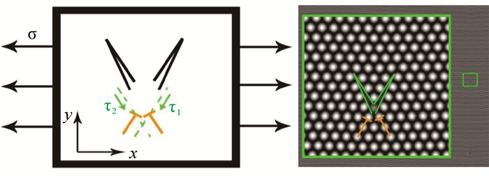
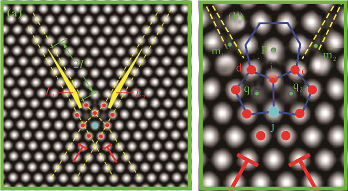
Zener裂纹通常是由局域位错塞积而产生,一端为开口裂尖,另一端为无开口裂尖,伴随有向错和位错的作用。因此,在模拟实验中要产生Zener裂纹,通过晶界位错形核起裂产生是最容易实现的。在PFC模拟实验中,可在最简单的小角晶界双晶样品的晶界上形成孤立位错,如图 2所示。加载应变以后,可以看到Zener裂纹的形核扩展,如图 3-6所示。之前的研究只是给出了连续介质力学的Zener裂纹,看不到Zener裂纹原子点阵的细节演化,而PFC模拟Zener裂纹形核长大,可以从原子分辨尺度揭示Zener裂纹演化细节过程。由图 3可以看到,Zener裂纹在位错处起裂[36],形成裂纹的张口,中间有一个空位缺陷。随着加载的应变增加,位错处的晶格原子发生移动并出现2个空位,对应于2个Zener裂纹的张口位置,空位周围有5个原子。由于原子的挤压运动,这2个空位上部1个原子周围有7个原子包围,形成七边形与五边形的晶格原子排列,构成了一对向错偶极子(图 4)。这对向错偶极子会对Zener裂纹产生强烈的拉和压的应变作用,构成了一对扭转力,将Zener裂纹沿滑移面劈开。Zener裂纹受力分析和向错结构如图 5(b)和(c)所示,向错偶极子的强度在图中标出,其中受挤压的七边形区域向错强度为-2ω,2个空位拉伸区域的五边形向错强度为ω+ω。此外,由图 6可见,Zener裂纹两侧的原子排列发生了扭转,角度差大约为8°。随着裂纹张口角度的扩大,裂纹两侧的晶列取向扭转角的差值也随之增加。

|
| σn means normal strain, σs means strain along slipping, α is the angle, ω means denote the disclination strength, and T denotes dislocation in the figure, P is the length of disclination, l is the length of crack, and B is Burgers vector of dislocation. 图 2 几种纳米裂纹的形核模型[12, 13, 18] Fig. 2 Nucleation models of several nanocracks[12, 13, 18] |

|
| σ: strain, τ: strain; L1 and L2 denote crack, t1 and t2 denote dislocation, ω denote the disclination strength.a1, b1, c1, d1, d2 denote the the vertex position of a triangle.m1, m2, q1, q2 are the positions of vacancy atoms, and p is the positions of atom. 图 5 双位错的裂纹萌生扩展[36] Fig. 5 Crack initiation and extension of double dislocations[36] |
2.2 裂尖楔形位错空隙发射
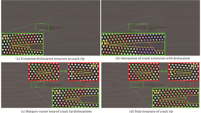
在裂纹扩展形核过程,除了应力集中外,在裂尖附近还会发生塑性变形。通常位错的发射可以释放集中的应力,使裂尖钝化。裂尖发射的位错有滑移运动类型和攀移运动类型,还有可能出现复杂的扩展复合位错。本课题组在运用PFC模型模拟裂纹扩展过程中观察到一种新的裂纹发射位错的现象[37, 38],发射的位错不是一个单一的位错,而是由两个广义扩展不全位错夹着一层楔形空隙构成的复合体[38]。如图 7所示,裂尖出现晶格排列的错位,形成扩展的位错结构(此扩展位错是不全位错),两个不全位错之间有一层空隙原子层,即裂纹空隙。在外应变作用下,畸变能增加;当外应变作用超过临界值时,裂尖将发生失稳,于是高畸变能区域的位错复合体从裂尖发射,释放畸变能,裂尖钝化,裂尖应力得以释放。由于这组扩展位错具有对称性,因此发射的位错复合体是一个楔形的扩展楔形位错空隙结构。裂纹发射位错后,裂尖钝化。
|
| 图 7 裂纹扩展与裂尖发射位错 Fig. 7 Crack extension and crack tip emitting dislocations |
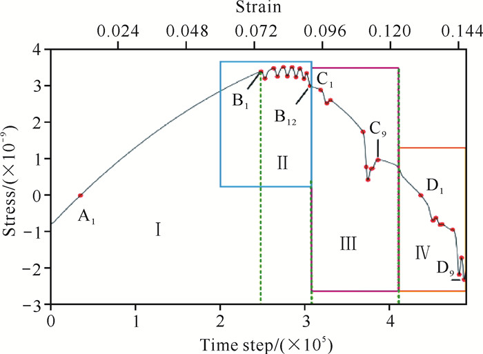
随着外加应变的增加,钝化的裂尖又萌生出新的锐裂尖,同时伴随台阶的产生。锐的裂纹继续扩展,当外应变作用再次达到临界值时,又重复上述的复合扩展位错体的发射。图 8给出了裂纹发射位错及其应变场分布图,可以看到裂尖处红色区域为应力集中的正拉伸应变区域;而蓝色区域为负应变区域,即压缩应变区域。随着裂纹区域的扩展,裂纹上下表面受到压缩应变作用(蓝色区域)。图 9给出了体系裂纹扩展过程中的应力-应变曲线。图 9中的峰位置B1、B2、……、B12对应的是钝裂尖克服不同位置的原子势垒的应变。图 9中曲线下降的谷位置C1-C9区间对应于裂尖发射位错的过程,表明发射位错的过程可以使裂尖区域的畸变能得到释放,裂尖应力集中得以舒缓。

|
| The figure in left side is the crack extension case, and the figure in right side is strain field distribution at the critical case of dislocation emission. 图 8 裂纹和对应的应变场分布 Fig. 8 Crack and corresponding strain field distribution |
|
| Ⅰ, Ⅱ, Ⅲ, Ⅳ denote different stages of the crack extension in figure; letters denote the positions of strain of different stages of the curve. 图 9 裂纹扩展与发射位错的体系应力-应变曲线 Fig. 9 Systematic stress-strain curves for crack extension and emission dislocations |
2.3 晶列取向对裂纹扩展的影响
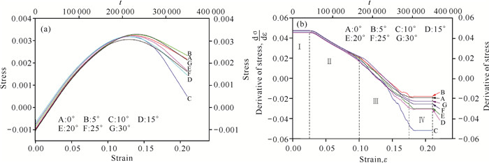
虽然已有关于裂纹形核扩展的模拟研究和韧-脆转变的实验研究报道[36],但是裂尖的位错组态对裂纹扩展模式的影响机理仍然没有明确[39]。对于实际晶体,裂纹扩展模式依赖于晶列的取向和裂尖位错与滑移晶面的关系。图 10给出了晶列取向角为15°情况下的裂纹扩展形貌和裂尖发射位错情况[40],此时的裂纹形貌边缘粗糙,裂尖钝化,存在许多微小的空洞,还伴随着位错的运动,裂纹像是一串串空洞生长串联起来的,是典型的韧性裂纹扩展模式。由图 10(b)可知,在A处发生裂纹转向并产生解理扩展,裂尖出现类似位错锁的组态结构。图 11给出了体系在裂纹扩展过程中的应力-应变曲线和应变变化率曲线图。由图 11(b)可以看出曲线可分成4个阶段,每段对应于体系变形的不同阶段:第一阶段对应弹性变形阶段,第二阶段对应塑性变形阶段,第三、第四阶段则进入断裂阶段,这时的应力变化率dσ/dε < 0。更详细的结果可参考Huang等[40]的研究。
2.4 裂纹扩展分叉
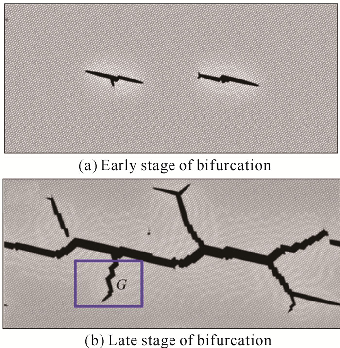
非平衡物理学和材料科学最具挑战的问题是材料裂纹扩展的模式选择,特别的是脆性材料中高速动态扩展的裂纹会发生分叉和速度振荡[39, 41, 42]。该分叉过程涉及动力过程的不稳定性和超弹性,也涉及裂尖的表面微观原子点阵的组态。图 12(a)-(h)是使用PFC方法施加双轴应变产生的裂纹分叉演化图[43]。由该演化图可知,当施加单轴拉伸应变时,裂纹主要为直线型扩展;随着应变的增加,裂纹开始出现台阶和转折,但不发生分叉。当y轴方向应变增加到某个临界值时,裂纹开始出现分叉萌芽[图 12(f)]。随着y轴方向的应变εy的增大,裂纹开始出现二次分叉,还伴随有位错发射[图 12(g)中的黑点],还可能进一步出现三级分叉[图 12(h)]。裂纹扩展的整个过程为解理脆性断裂,但在转折分叉处出现发射位错的现象,说明裂纹分叉是非稳定状态。Deng等[39]给出了裂纹的速度振荡特征;另外,裂尖分叉的应变集中现象也可在PFC方法模拟的裂纹中观察到[44]。如图 13所示,PFC方法还模拟了裂纹的连通和分叉,两个扩展的裂纹连通后开始二次分叉,主裂纹最粗,分叉的子裂纹较细。由于选用的模拟晶格为六角对称,因此裂纹分叉主要是沿解理面(晶列取向)方向进行,其主要裂纹分叉的夹角大约分为60°和120°两种情况[44]。
2.5 裂纹扩展与位错的相互作用
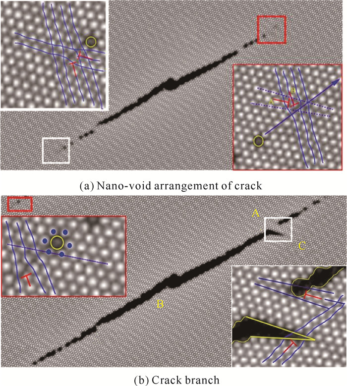
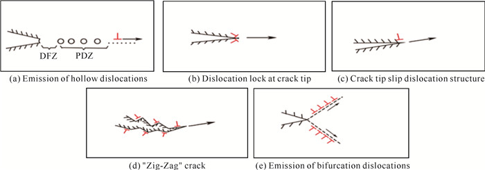
本课题组曾应用PFC方法研究裂纹扩展的裂尖与位错的相互作用,观察裂纹扩展模式的转变[40-45]。由此可归纳出5种位错与裂尖关系,如图 14所示。第1种关系如图 14(a)所示,从缺口发射的位错沿变形滑移面滑移,产生了一串串纳米空洞,这些空洞生长连通形成表面粗糙的裂纹,为典型的韧性裂纹,这一过程主要是塑性变形的韧性断裂。第2种关系如图 14(b)所示,为脆性断裂的裂纹扩展模式。这时的裂尖存在一对位错锁并对称于解理面,位错锁的Burgers矢量方向垂直于裂纹的解理面。当裂纹扩展时,由于位错锁是不可动位错,在外部施加的应变力作用下,位错锁区域发生局部应变集中并产生强烈应变,将裂尖前的原子键打断,从而发生解理扩展,这时宏观上的裂纹表面是整齐光滑的。第3种关系如图 14(c)所示,在裂尖的一侧边缘存在着一个位错,并随着裂尖沿解理面扩展。该位错并不能从裂尖发射出去,这是由于位错的滑移速度与裂纹扩展的速度相等,或小于裂纹扩展的速度。这种关系的裂纹属于脆性解理裂纹。第4种关系如图 14(d)所示,解理扩展通过裂尖的方向交替转向进行。在裂纹转向的位置存在位错交错排列,位错并不能发射出去。在裂纹扩展过程中,沿着裂纹的边缘形成了光滑的锯齿状结构。这种关系的裂纹扩展,属于解理脆性断裂。第5种关系如图 14(e)所示,裂尖连续向裂纹两侧发射位错,裂纹钝化,或者向一侧发射位错,或者沿扩展方向发射复合位错。在高温的情况下,应用PFC方法模拟也能看到位错发射的现象,这种模式的裂纹扩展,属于韧性断裂行为。
韧性断裂模式的转变,都与裂尖是否出现塑性变形区、发射位错相关,因此Huang等[40]提出了复合应力强度因子的概念,用于建立裂尖原子动力学模型,计算了裂尖发生解理扩展和裂尖发射位错的临界应力强度因子的条件,并给出了施加的应变、晶列取向的角度与应力强度因子的关系,由此得到韧-脆裂纹模式转变的判据。Gao等[41]给出了裂尖势函数与裂尖原子位移的函数关系,并讨论了临界应力强度因子对韧-脆裂纹扩展的影响。
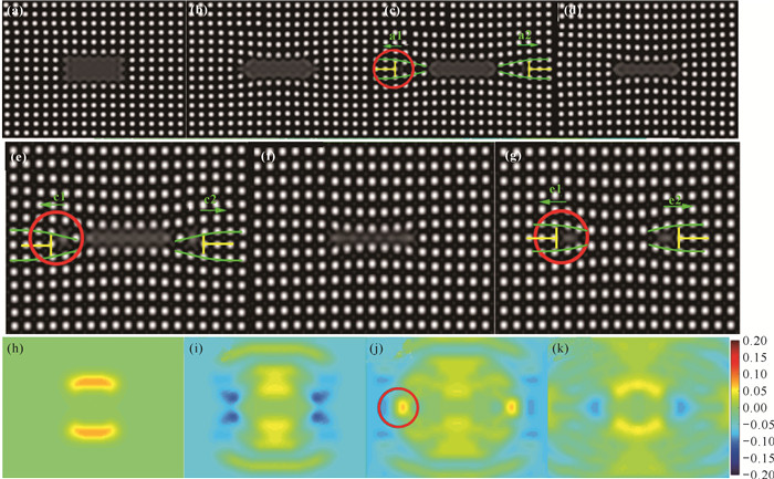
2.6 纳米孔洞裂纹的愈合修复裂纹、孔洞等缺陷在材料的加载条件下会发生扩展长大,对材料产生破坏性作用。近年来已经开展了许多关于裂纹修复愈合的研究[46-48]。由于裂纹愈合过程中涉及原子的扩散运动,因此需要在纳观尺度下研究材料裂纹修复愈合的机理。图 15(a)-(g)给出了PFC模拟空洞裂纹愈合的微观过程。由图 15(b)可见,矩形裂纹缺口的上下面发生内向弯曲,左右两侧出现向外凸出的小缺口,相当于萌生出新的裂尖,进而发射位错,使裂尖钝化。此时,矩形的裂纹上下宽度收缩一个原子厚度,相当于修复了一层原子,然后萌生新的裂尖,再次发射位错,裂尖发生钝化,裂纹厚度又减少一层原子。经过多次的发射位错和裂尖钝化,裂纹缺口最终实现了愈合修复。图 15(h)-(k)给出了裂纹缺口修复过程的应变场分布,裂口上下存在膨胀应变分布(黄色区域),促使裂口上下表面愈合;而在裂口的两侧,则存在压缩应变(蓝色区域),对应于两侧的原子受到外向的挤压,同时对应于位错的发射运动。上述结果与实验观察是相符合的。
|
| 图 15 孔洞裂纹愈合过程与对应的应变场分布 Fig. 15 Void crack healing process and corresponding strain field distribution |
3 展望
由于PFC模型具有空间原子分辨特征尺度和扩散时间尺度特征,因此在扩散时间尺度上模拟材料原子尺度的微结构演化具有突出的优势。针对裂纹形核、萌生、起裂和分叉的模拟,PFC模型可从以下3个方面进行改进和发展:①通过与具体材料的原子相互作用函数的结合,使PFC模型内在的弹塑性特征量与实际材料的宏观参量桥接,应用到具体材料的宏观性能研究上,使之更具有实用性;②发展振幅的PFC模型,使得PFC模型具有多个时间和空间特征尺度,适应多尺度的介观-微观-纳观范围的体系研究,从而模拟更复杂结构的裂纹萌生扩展演化;③研究更先进的求解高阶非线性微分方程的数值算法,提高计算精度和效率,节省计算时间。今后应用PFC模型对裂纹研究的重点主要集中在以下5个方面:晶界、三叉晶界的裂纹萌生扩展,以及复杂晶体的Zener纳米裂纹的形核机理;蠕变过程中的位错空洞裂纹的萌生机理;裂尖扩展位错结构组态转变对韧-脆转变的影响;裂尖发射复杂位错组态结构和楔形位错空隙的机理;晶体材料裂纹与不同组态位错相互作用对裂纹周围的结构影响。可以预见,PFC模型为研究晶体材料的纳米空洞、裂纹萌生、扩展分叉、断裂的纳观机理提供越来越重要的指导作用。
| [1] |
SAKA H, AGATA Y. Direct evidence for dislocation-free zone in Fe-5% Si fractured by Charpy impact test[J]. Materials Science and Engineering: A, 2003, 350(1/2): 57-62. |
| [2] |
ZHAO Y, FANG Q, LIU Y, et al. Dislocation emission from nanovoid with the effect of neighboring nanovoids and surface stresses[J]. International Journal of Solids and Structures, 2014, 51(7/8): 1617-1629. |
| [3] |
PINEAU A, BENZERGA A A, PARDOEN T. Failure of metals Ⅰ: brittle and ductile fracture[J]. Acta Materialia, 2016, 107: 424-483. DOI:10.1016/j.actamat.2015.12.034 |
| [4] |
MARSH P G, ZIELINSKI W, HUANG H, et al. Crack-tip dislocation emission arrangements for equilibrium-Ⅲ.Application to large applied stress intensities[J]. Acta Metallurgica et Materialia, 1992, 40(11): 2883-2894. DOI:10.1016/0956-7151(92)90453-L |
| [5] |
YANG W, TANG J C, ING Y S, et al. Transient dislocation emission from a crack tip[J]. Journal of the Mechanics and Physics of Solids, 2001, 49(10): 2431-2453. DOI:10.1016/S0022-5096(01)00046-1 |
| [6] |
RICE J R. Dislocation nucleation from a crack tip: an analysis based on the Peierls concept[J]. Journal of the Mechanics and Physics of Solids, 1992, 40(2): 239-271. DOI:10.1016/S0022-5096(05)80012-2 |
| [7] |
ARGON A S. Brittle to ductile transition to cleavage fracture[J]. Acta Metallurgica, 1987, 35(1): 185-196. DOI:10.1016/0001-6160(87)90228-8 |
| [8] |
YASHIRO K. Local lattice instability analysis on mode Ⅰ crack tip in hcp-Mg: unstable mode for crack propagation vs.dislocation emission[J]. Computational Materials Science, 2017, 131: 220-229. DOI:10.1016/j.commatsci.2017.02.004 |
| [9] |
GE J, SUN Y, WANG T, et al. Fatigue crack growth based on the dislocation-free zone (DFZ) model[J]. Engineering Fracture Mechanics, 2015, 149: 111-118. DOI:10.1016/j.engfracmech.2015.10.001 |
| [10] |
ZHOU K, NAZAROV A A, WU M S. Continuum and atomistic studies of a disclinated crack in a bicrystalline nanowire[J]. Physical Review B, 2006, 73(4): 045410. DOI:10.1103/PhysRevB.73.045410 |
| [11] |
MICHOT G, DE OLIVEIRA M A L, CHAMPIER G. A model of dislocation multiplication at a crack tip: influence on the brittle to ductile transition[J]. Materials Science and Engineering: A, 1999, 272(1): 83-89. DOI:10.1016/S0921-5093(99)00473-6 |
| [12] |
WU M S. Energy analysis of Zener-Griffith crack nucleation from a disclination dipole[J]. International Journal of Plasticity, 2018, 100: 142-155. DOI:10.1016/j.ijplas.2017.10.001 |
| [13] |
FAN H, XIAO Z M. A Zener-Stroh crack near an interface[J]. International Journal of Solids and Structures, 1997, 34(22): 2829-2842. DOI:10.1016/S0020-7683(96)00196-5 |
| [14] |
FAN M, YI D K, XIAO Z M. A Zener-Stroh crack interacting with a coated inclusion with generalized Irwin plastic zone correction[J]. International Journal of Solids and Structures, 2014, 51: 3399-3409. DOI:10.1016/j.ijsolstr.2014.06.007 |
| [15] |
WU M S. Characteristics of a disclinated Zener crack with cohesive end zones[J]. International Journal of Engineering Science, 2001, 39(13): 1459-1485. DOI:10.1016/S0020-7225(00)00086-0 |
| [16] |
ZHUANG J, XIAO Z. Generalized Irwin plastic zone correction of a sub-interface Zener-Stroh crack in a coating-substrate system[J]. International Journal of Mechanical Sciences, 2015, 94/95: 123-130. DOI:10.1016/j.ijmecsci.2015.02.015 |
| [17] |
WU M S, HE M D. Interaction of wedge crack and grain boundary dislocations[J]. International Journal of Solids and Structures, 1998, 35(31/32): 4337-4350. |
| [18] |
WU M S. Characteristics of a Zener crack wedged open by a disclination dipole[J]. Solid State Phenomena, 2002, 87: 277-300. DOI:10.4028/www.scientific.net/SSP.87.277 |
| [19] |
WANG T, LUO J, XIAO Z, et al. On the nucleation of a Zener crack from a wedge disclination dipole in the presence of a circular inhomogeneity[J]. European Journal of Mechanics-A/Solids, 2009, 28(4): 688-696. DOI:10.1016/j.euromechsol.2009.03.006 |
| [20] |
ADELZADEH M, SHODJA H M, RAFII-TABAR H. Computational modeling of the interaction of two edge cracks, and two edge cracks interacting with a nanovoid, via an atomistic finite element method[J]. Computational Materials Science, 2008, 42(2): 186-193. DOI:10.1016/j.commatsci.2007.07.012 |
| [21] |
TAN H, YANG W. Atomistic/continuum simulation of interfacial fracture-Part Ⅱ: atomistic/dislocation/continuum simulation[J]. Acta Mechanica Sinica, 1994, 10(3): 237-249. DOI:10.1007/BF02487612 |
| [22] |
GUO Y F, WANG C Y, ZHAO D L. Atomistic simulation of crack cleavage and blunting in bcc-Fe[J]. Materials Science and Engineering A, 2003, 349(1/2): 29-35. |
| [23] |
STEFANOVIC P, HAATAJA M, PROVATAS N. Phase field crystal study of deformation and plasticity in nanocrystalline materials[J]. Physical Review E, 2009, 80(4): 046107. DOI:10.1103/PhysRevE.80.046107 |
| [24] |
ELDER K R, GRANT M. Modeling elastic and plastic deformations in nonequilibrium processing using phase field crystals[J]. Physical Review E, 2004, 70(5): 051605. DOI:10.1103/PhysRevE.70.051605 |
| [25] |
TRAUTT Z T, ADLAND A, KARMA A, et al. Coupled motion of asymmetrical tilt grain boundaries: molecular dynamics and phase field crystal simulations[J]. Acta Materialia, 2012, 60(19): 6528-6546. DOI:10.1016/j.actamat.2012.08.018 |
| [26] |
MELLENTHIN J, KARMA A, PLAPP M. Phase-field crystal study of grain-boundary premelting[J]. Physical Review B, 2008, 78(18): 184110. DOI:10.1103/PhysRevB.78.184110 |
| [27] |
ADLAND A, KARMA A, SPATSCHEK R, et al. Phase-field-crystal study of grain boundary premelting and shearing in bcc iron[J]. Physical Review B, 2013, 87(2): 024110. DOI:10.1103/PhysRevB.87.024110 |
| [28] |
OLMSTED D L, BUTA D, ADLAND A, et al. Dislocation-pairing transitions in hot grain boundaries[J]. Physical Review Letters, 2011, 106(4): 046101. DOI:10.1103/PhysRevLett.106.046101 |
| [29] |
GAO Y J, HUANG L L, DENG Q Q, et al. Phase field crystal simulation of dislocation configuration evolution in dynamic recovery in two dimensions[J]. Acta Materialia, 2016, 117: 238-251. DOI:10.1016/j.actamat.2016.06.021 |
| [30] |
GAO Y J, DENG Q Q, LIU Z Y, et al. Modes of grain growth and mechanism of dislocation reaction under applied biaxial strain: atomistic and continuum modeling[J]. Journal of Materials Science & Technology, 2020, 49: 236-250. |
| [31] |
TAKAKI T, TOMITA Y. Static recrystallization simulations starting from predicted deformation microstructure by coupling multi-phase-field method and finite element method based on crystal plasticity[J]. International Journal of Mechanical Sciences, 2010, 52(2): 320-328. DOI:10.1016/j.ijmecsci.2009.09.037 |
| [32] |
TIAN X L, ZHAO Y H, PENG D W, et al. Phase-field crystal simulation of evolution of liquid pools in grain boundary pre-melting regions[J]. Transactions of Nonferrous Metals Society of China, 2021, 31(4): 1175-1188. DOI:10.1016/S1003-6326(21)65570-X |
| [33] |
WU K, ADLAND A, KARMA A. Phase-field-crystal model for fcc ordering[J]. Physical Review E, 2010, 81(6): 061601. |
| [34] |
MKHONTA S K, ELDER K R, HUANG Z F. Exploring the complex world of two-dimensional ordering with three modes[J]. Physical Review Letters, 2013, 111(3): 035501. DOI:10.1103/PhysRevLett.111.035501 |
| [35] |
ELDER K R, HUANG Z F, PROVATAS N. Amplitude expansion of the binary phase-field-crystal model[J]. Physical Review E, 2010, 81(1): 011602. |
| [36] |
LIU Z Y, GAO Y J, DENG Q Q, et al. A nanoscale study of nucleation and propagation of Zener types cracks at dislocations: phase field crystal model[J]. Computational Materials Science, 2020, 179: 109640. DOI:10.1016/j.commatsci.2020.109640 |
| [37] |
邓力滔, 卢昱江, 刘哲源, 等. 晶体相场法模拟晶界萌生裂纹扩展机理[J]. 广西科学, 2018, 25(6): 658-662. |
| [38] |
DENG Q Q, GAO Y J, LIU Z Y, et al. Atomistic simulation of void growth by emitting dislocation pair during deformation[J]. Physica B: Condensed Matter, 2020, 578: 411767. DOI:10.1016/j.physb.2019.411767 |
| [39] |
DENG Q Q, GAO Y J, LIAO K, et al. Energy model of transformation of two-time decomposition mode of dislocation structure at triple junction: ultra-fine grained materials[J]. Mechanics of Materials, 2022, 173: 104438. DOI:10.1016/j.mechmat.2022.104438 |
| [40] |
HUANG L L, GAO Y J, DENG Q Q, et al. A study of relationship between dislocation configuration of nanocrack and brittle-ductile mode of fracture: atomistic modeling[J]. Computational Materials Science, 2020, 173: 109413. DOI:10.1016/j.commatsci.2019.109413 |
| [41] |
GAO Y J, DENG Q Q, HUANG L L, et al. Atomistic modeling for mechanism of crack cleavage extension on nano-scale[J]. Computational Materials Science, 2017, 130: 64-75. DOI:10.1016/j.commatsci.2017.01.003 |
| [42] |
LU Y J, GAO Y J, DENG Q Q, et al. Effect of crystal orientation on initiation and propagation of crack: phase field crystal model study[J]. The European Physical Journal B, 2019, 92: 194. DOI:10.1140/epjb/e2019-100117-y |
| [43] |
GAO Y J, LUO Z R, HUANG L L, et al. Phase field crystal study of nano-crack growth and branch in materials[J]. Modelling and Simulation in Materials Science and Engineering, 2016, 24(5): 055010. DOI:10.1088/0965-0393/24/5/055010 |
| [44] |
高英俊, 罗志荣, 黄礼琳, 等. 韧性材料的微裂纹扩展和连通的晶体相场模拟[J]. 中国有色金属学报, 2013, 23(7): 1892-1899. |
| [45] |
GAO Y J, HUANG Z J, DENG Q Q, et al. Structural transformation and energy analysis for pile-up dislocations at triple junction of grain boundary[J]. Transactions of Nonferrous Metals Society of China, 2022, 32(1): 45-63. DOI:10.1016/S1003-6326(21)65777-1 |
| [46] |
LI Y X, GAO Y J, LIAO K, et al. Center atom model for strain mapping of void and crack of atomic lattice image[J]. Crystal Research and Technology, 2022, 57(10): 2100264. DOI:10.1002/crat.202100264 |
| [47] |
LI Y X, GAO Y J, YI X A, et al. Phase field crystal simulation of gap healing at nanoscale[J]. Modelling and Simulation in Materials Science and Engineering, 2022, 30(6): 064004. DOI:10.1088/1361-651X/ac8174 |
| [48] |
宁岁婷, 胡绪志, 黄礼琳, 等. 三角缺口与圆形缺口起裂和裂纹扩展的晶体相场模拟[J]. 广西科学, 2017, 24(6): 540-544, 550. |


